ODROID-VU8C : 8inch Touch Display Shell Kit

ODROID-VU8C : 8inch Touch Display Shell Kit

Model: (DEV-00190)
Status: Unavailable

ODROID-VU8C: 8inch Touch Display Shell Kit


Multi-touch screen 8inch-C2 and C1 + for Odroid
It gives users the ability to create all-in-one, integrated projects such as tablets, game consoles, infotainment systems and embedded systems. 

Just input a 5V / 4A DC to the LCD Shell and power up the C2 and C1 + as well as display.  
This high-quality wide viewing angle LCD touchscreen is specifically designed to work with both Android and Linux on the ODROID-C1 + and ODROID-C2.
Specifications

- 8-inch TFT-LCD
- Screen Resolution: 1024x768 pixels (4: 3 ratio)
- 10 finger capacitive touch input (USB ID 18D1: 4E12)
- Back-light brightness control PWM with Odroid GPIO
- Max Power consumption: 1.1A / 5Volt (Only LCD and display controller)
- Viewing angle: Left 75, Right 75, 75 Up, Down 75 degree
- Screen Dimensions: 189 x 149 x 29 mm 
- Viewable screen size: 162 X121.5 mm (active area)

Detail guide:  Http://Odroid.com/Dokuwiki/Doku.php?Id=En:acc:vu8


$ 90.00108,000 원 (부가세 별도)
Worldwide shipping
한국 배송 (Korean only)
VU8.jpg
VU8parts.jpgPackage include

8inch TFT LCD + 10 points multi touch screen A. Assembled
Plastic bottom case B.
C. Converter board
gender dual HDMI board D.
E. 8 x 3.5mm screws 
F. 2port jumper cable
G. Micro-to-Micro USB Cable (approx. 8cm)
Micro-to-TypeA H. USB Cable (approx. 20cm) 
I. 5V / 4A Power supply
 

OS UPDATE

Odroid-C1 / C1 + / C2 (Edit boot.ini file)

Touchscreen drivers are available with support for 10 touch points, and 
proper drivers are integrated in the latest Ubuntu and Android OS images. Screen resolution must be configured to WVGA (1024x768) and the DVI 
option should be enabled on the "v out" parameter by editing the boot.ini 
file, as shown in the below. 

To use the VU 8  on C1 / + Linux system, the Kernel version must be 
3.10.80-128 or higher (sudo apt-get update sudo apt-get dist-upgrade &) .
 
Also, do not forget to configure the boot.ini file like this for  1024x768  resolution and  DVI  output mode: 

Configuration for C0 / C1 / C1 + / C2 (Edit boot.ini file)
out and uncomment the line 1080p Comment 1024x768 enable line " DVI "option.
.
.
# Setenv m "1080p" 1080p @ 60Hz # 
.
.
setenv m "1024X768P60Hz" 
.
.
.
# HDMI DVI Mode Configuration 

setenv v out "DVI"
 for  C2 .

setenv Vout_Mode "DVI"
 for  C1 / C1 + / C0
.

VU8_a.jpgVU8_b.jpgVU8_c.jpg
Ethernet port and 2x USB host ports

Vent hole and cutting line for the 40pin GPIO port. 5V / 4A PSU input


VU8_C2.jpgVU8_C1.jpg
ASSEMBLY GUIDE

Please take special care when assemble it.

VU8Ass0.jpgPlug the HDMI dual gender board to the converter board. It is easier to fit the HDMI dual gender board with this angle. 
VU8Ass01.jpgPlug it tight. Check the connector. 
VU8Ass02.jpgPlug the ODROID-C2 / C1 + to the other connector on the HDMI dual gender board. 
VU8Ass03.jpgPlug it tight for stable HDMI connectivity. 
VU8Ass04.jpgThe HDMI signal is connected. 
VU8Ass30.jpgSkip this process if backlight control is not necessary. 

Add the script to "/etc/rc.local" in your source code for backlight control.
Http://Odroid.com/Dokuwiki/Doku.php?Id=En:acc:vu8

Plug the jumper cable to the GPIO pin # 33 and # 35. 
Plug the other side of the cable to the converter board. Please check the color of the cable in the picture again.
VU8Ass31.jpgCheck the place of the pin. 
VU8Ass07.jpgPlug the micro to micro USB cable. 
It gives the C2 or C1 + the power via the converter board. 
You are supposed to input 5V / 4A PSU to the converter board for the whole system. 
VU8C_add1.jpgThe two jumper pins must be plugged to input the power via the microUSB connector. 
VU8Ass08.jpgPlug the standard to micro USB cable for touch signal between C2 / C1 + and converter board. 
VU8Ass09.jpgPlace the assembled board on the bottom case and put the screws. 
VU8Ass10.jpgPut screws on the screw hole of the C2 / C1 + board. 
VU8Ass11.jpgInstall the eMMC Module / MicroSD card. 
It is not possible changing the eMMC module or microSD card after full assembly. 
VU8Ass12.jpgSlide out open the 40pin connector slot. 
VU8Ass14.jpgInsert the 40pin FPCB into the connector slot. 
The LCD signal goes to the converter board via this FPCB. 
VU8Ass15.jpgLock the slot. 
VU8Ass18.jpgOpen the 6pin connector. The door must open by 90degree up.
VU8Ass19.jpgInsert the 6pin FPCB into the connector carefully with tweezers.
The dark part must be inserted correct. 
The touchscreen signal goes to the converter board via this 6pin FPCB.

This is one of the most difficult step. If the 6pin FPCB is not inserted correct, it will be loosen and touch signal disconnected. 
VU8Ass20.jpgClose the door. 
VU8Ass21.jpgCheck the 40pin and 6pin FPCBs connection. 

LCD: 40Pin / 20.5Mm
Touch screen: 6pin / 3.5mm
VU8Asscaselocking.jpgCheck the hooks and locking holes on the bottom case before you close the front piece.
VU8Ass22.jpgClose the case. 
Make sure not to damage the FPCBs and system inside the case which is fragile. 
VU8Ass23.jpgPress the side of the bottom case reasonably hard to hook the locking parts. 
Check the location of hook and locking parts. 
VU8Ass32.jpgPut the screws on 4 corner side of the screw hole. 

BLOCK DIAGRAM
Vu8_blockdiagram.001.jpg
BOARD DETAIL

VU8_C1_LAYOUT.png


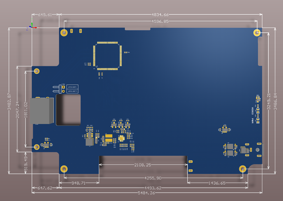
Known issues.
1. It is very hard to assemble and disassemble due to complicated mechanical design. 
Be careful when you open the cover. Otherwise, you will break the LCD interface flexible cable.
2. Old OS images might not support the touch screen. You need to update the OS or Kernel.
Write new review
All Categories
Related Articles
There is no article related to this product.
Your browser is Out-Of-Date!
Update your browser to view this website correctly. Update Browser Now
×