شیلد نمایشگر LCD TFT فول کالر 2.4 اینچ با درایور Ili9341 برای آردوینو UNO تاچ مقاومتی
The shield is fully assembled, tested and ready to go. No wiring, no soldering! Simply plug it in and load up our library - you'll have it running in under 10 minutes! Works best with any classic (UNO/Duemilanove/Diecimila). This shield does NOT work with the Mega but its going to be half the speed of the Uno-type boards because of the way the Mega rearranges all the pins (there is no way to get around this!) This shield is not Leonardo-compatible
Description:
Spice up your project with a beautiful large touchscreen display shield with built in microSD card connection. This TFT display is big (2.4" diagonal) bright (4 white-LED backlight) and colorful (18-bit 262,000 different shades)! 240x320 pixels with individual pixel control. It has way more resolution than a black and white 128x64 display. As a bonus, this display has a resistive touchscreen attached to it already, so you can detect finger presses anywhere on the screen.
Technical Details:
2.4" diagonal LCD TFT display
240x320 resolution, 18-bit (262,000) color
spfd5408 controller with built in video RAM buffer
8 bit digital interface, plus 4 control lines
Uses digital pins 5-13 and analog 0-3. That means you can use digital pins 2, 3 and analog 4 and 5. Pin 12 is available if not using the microSD
Works with any '328 or Mega (Leonardo not supported yet)
5V compatible! Use with 3.3V or 5V logic
Onboard 3.3V 300mA LDO regulator
4 white LED backlight. On by default but you can connect the transistor to a digital pin for backlight control
4-wire resistive touch screen
" id="Product_Picture" style="color:#0000ff">Product Picture


Product Description
- Supports development boards such as Arduino UNO and Mega2560 for plug-in use without wiring
- 320X240 resolution, clear display, support for touch function
- Support 16-bit RGB 65K color display, display rich colors
- 8-bit parallel bus, faster than serial SPI refresh
- On-board 5V/3.3V level shifting IC, compatible with 5V/3.3V operating voltage
- Easy to expand the experiment with SD card slot
- Provides an Arduino library with a rich sample program
- Military-grade process standards, long-term stable work
- Provide underlying driver technical support
Product Parameters
| Name | Parameter |
| Display Color | RGB 65K color |
| SKU | MAR2406 |
| Screen Size | 2.4(inch) |
| Type | TFT |
| Driver IC | ILI9341 |
| Resolution | 320*240 (Pixel) |
| Module Interface | 8-bit parallel interface |
| Active Area | 48.96*36.72(mm) |
| Module PCB Size | 72.20*52.7(mm) |
| Operating Temperature | -20℃~60℃ |
| Storage Temperature | -30℃~70℃ |
| Operating Voltage | 5V/3.3V |
| Power Consumption | TBD |
| Product Weight(Package containing) | 39(g) |
Interface Definition

| Number | Pin Label | Pin Description |
| 1 | LCD_RST | LCD bus reset signal, low level reset |
| 2 | LCD_CS | LCD bus chip select signal, low level enable |
| 3 | LCD_RS |
LCD bus command / data selection signal, low level: command, high level: data |
| 4 | LCD_WR | LCD bus write signal |
| 5 | LCD_RD | LCD bus read signal |
| 6 | GND | Power ground |
| 7 | 5V | 5V power input |
| 8 | 3V3 | 3.3V power input, this pin can be disconnected |
| 9 | LCD_D0 | LCD 8-bit data Bit0 |
| 10 | LCD_D1 | LCD 8-bit data Bit1 |
| 11 | LCD_D2 | LCD 8-bit data Bit2 |
| 12 | LCD_D3 | LCD 8-bit data Bit3 |
| 13 | LCD_D4 | LCD 8-bit data Bit4 |
| 14 | LCD_D5 | LCD 8-bit data Bit5 |
| 15 | LCD_D6 | LCD 8-bit data Bit6 |
| 16 | LCD_D7 | LCD 8-bit data Bit7 |
| 17 | SD_SS | SD card SPI bus chip select signal, low level enable |
| 18 | SD_DI | SD card SPI bus MOSI signal |
| 19 | SD_DO | SD card SPI bus MISO signal |
| 20 | SD_SCK | SD card SPI bus clock signal |
Connect to Arduino
 |
 |
|---|---|
| Arduino UNO direct insertion picture | Arduino Mega2560 direct insertion picture |
How to use on Arduino
- Step 1: Download the test program
- Download the Arduino test program from the Program Download column
- For a description of the relevant test procedures, please refer to the test program documentation in the package
- Step 2: Connect the Arduino development board
- Plug the module directly into the Arduino development board ( Do not plug in?)
- After the module is plugged in, power on the Arduino board
- Step 3: Copy the dependent library
- Make sure the Arduino IDE is installed on your computer (if it is not installed: Arduino IDE download URL)
- After installing the Arduino IDE, you need to copy the dependent library to the Arduino project directory as follows:
-
- (1) Decompress the downloaded test package
- (2) Copy the dependent libraries in the Install libraries directory in the package (shown below) to the libraries folder
-
- of the Arduino project directory ( Don't know the Arduino project directory?)
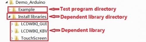

- Step 4: Compile and download the program to the development board
- Open the sample in the Example directory of the package to test, compile and download( Don't know how to compile and download?)
- Step 5: Observe the running of the program
- After the program is downloaded, run it directly and observe the running status. If it can be displayed normally, the program runs
-
- successfully, as shown in the following figure (take the colligate_test test program as an example):


Program Download
Product Documentation
- 2.4 inch Arduino UNO Module User Manual
- 2.4 inch Arduino UNO Module Size Picture
- 2.4 inch TFT Specifications
- 2.4 inch QD243701 TFT LCD Schematic and PCB Package Library
- Driver IC ILI9341 Data sheet
Reference Materials
- Arduino IDE software use illustration
- C51 Keil and stc-isp software use illustration
- STM32 keil software use illustration
- PCtoLCD2002 software use illustration
- Image2Lcd software use illustration
- Chinese and English display modulo settings
Common Software