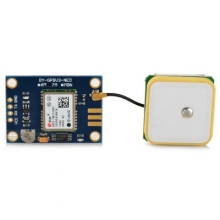
The U-blox NEO-7M GPS Module is ideal for all sorts of development boards, Arduino projects and more. It can operate on voltages between 3 and 6V DC, and has a simple serial output which blasts out the NMEA GPS data at 9600 baud.
Arduino users - this works perfectly with the TinyGPS++ library. With the 7M you can also extract navigation data with this Arduino library.
Specfications:
Pinouts:
- GND - GND
- Vcc - connect to 5V or 3.3V
- TX - data from GPS module - connect to your board's RX pin
- RX - data to the GPS module - connect to your board's TX pin
- PPS - time pulse output
More information:
Introduction
GPS module that uses GPS and GLONASS satellites.
- Specifications:
-
Wiring
A GPS receiver is rather ‘chatty’, so it is strongly advised to use hardware serial ports.
The ESP8266 only has 2 HW serial ports, but only Serial0 uses a HW RX pin. The TX channel from the ESP to the GPS is not needed for this plugin.
The used baudrate is 9600 bps.
ESP                         Neo-7M (HW Serial0)
GPIO (3/RX/RX0/D9)   <-->   TXD
GPIO (1/TX/TX0/D10)  <-->   RXD
ESP                         Neo-7M (HW Serial0 swapped)
GPIO (13/D7)         <-->   TXD
GPIO (15/D8)         <-->   RXD
ESP                         Neo-7M (HW Serial1)
not used             <-->   TXD
GPIO (2/D4)          <-->   RXD
Power
5.0V                 <-->   VCC
GND                  <-->   GND
Danger
If you use HW Serial0 or HW Serial0 swapped you must disable serial port in the advanced settings! If you fail to do so the unit will not work properly.
Setup
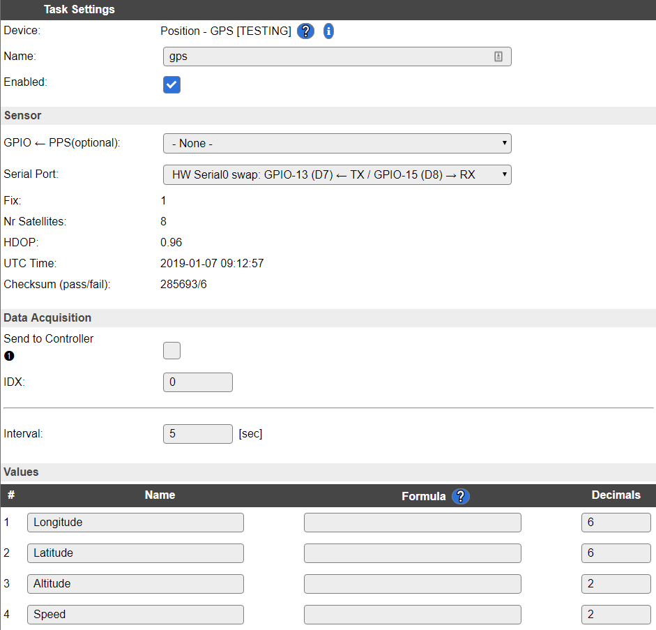
A screenshot of a later relase of the plugin. The use of hardware serial communication makes the transfer between the GPS and ESP a LOT more stable:
Task settings
- Device: Name of plugin
- Name: Name of the task (example name GeoPos)
- Enable: Should the task be enabled or not
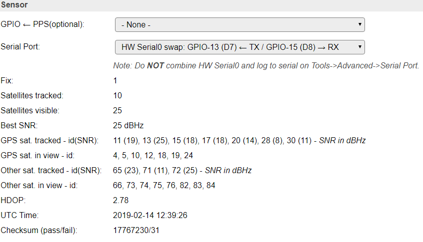
Sensor
- GPIO <– TX: Used to communicate with the GPS unit.
- GPIO –> RX: Not used (optional), to push commands back into the GPS unit.
- GPIO –> PPS: Experimental (optional), used to let the GPS unit update the time of the ESP.
-
- Dropdown:
SoftwareSerial lets you select any GPIO pin, HW Serial0 is the preferred (most stable),
HW Serial0 swapped is similar to Serial0, HW Serial1 is only able to receive data from the GPS unit.
Warning
It’s highly recommended you use either the HW Serial1 or HW Serial0 for stable reading of the GPS unit. But also remember to disable the serial in the advanced settings page, if not the ESP will interfere with the GPS unit.
PPS pin
Some GPS receivers have a PPS pin. This can be used to get a very accurate time reference. According to Wikipedia this signal could be considered a “stratum-1 time source”.
The signal on the PPS pin is a high pulse of +/- 100 msec and the rising edge signals the start of a second. The time reported after this pulse describes the past rising edge of the PPS pulse.
Note
Currently the PPS feature is not thoroughly tested yet, so consider it experimental.
Data acquisition
- Send to controller 1..3: Check which controller (if any) you want to publish to. All or no controller can be used.
- Interval: How often should the task publish its value (5..15 seconds is normal).
Indicators (recommended settings)
| Indicator |
Value Name |
Interval |
Decimals |
Extra information |
| Longitude |
Long |
1 |
6 |
5 decimals = 100cm resolution, 6 decimals = 10cm resolution, 7 decimals = 1cm resolution |
| Latitude |
Lat |
1 |
6 |
5 decimals = 100cm resolution, 6 decimals = 10cm resolution, 7 decimals = 1cm resolution |
| Altitude |
Alt |
1 |
0 |
Normally only full meters are needed. Use more decimals if you need higher resolution. |
| Speed |
mps |
1 |
1 |
Meters per second. |
Note
These resolutions are given at the equator. Less accuracy is received the further north/south you go.
Rules examples
on GeoPos#Speed do
 if [GeoPos#Speed]>50
   //Whooohooo, fast as lightning!
 endif
endon
Events
| Event |
Example |
GPS#GotFix Will trigger when the GPS unit got a good position from the satellites. |
on GPS#GotFix do
 GPIO,2,1 //LED on
endon
|
GPS#LostFix Will trigger when the GPS unit is not having a good position from the satellites. |
on GPS#LostFix do
  GPIO,2,0 //LED off
endon
|